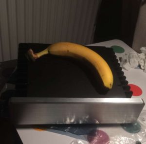
banana for scale
This was a highly anticipated and fun build. I record music, so I’ve always wanted quiet/silent PCs that can live in the same room as recording equipment. My first build was in 2002 or so, and it mostly employed a sound-dampening case and a quieter-than-stock heatsink/fan combo to reduce noise. Around 2008, it was time to upgrade and I  built my second quiet/silent PC using a newer version of the same sound-dampening Antec case, a fanless video card, and the quietest cpu/case fans I could find. It was quiet, although not silent, but did the job to allow for audio recordings for many years.
As 2017 approached, my beat-up case was showing severe wear and tear from years of use and then being shipped halfway around the world, and by this point was supporting 6 hard drives, 4 fans, a blu-ray drive and a video card, which pulled over 1.5A every time it was turned on. Because the case was in  such bad shape, the formerly quiet PC was becoming quite loud, and the many mechanical HDDs accrued over the intervening time added even more to the sound. Even though the PC was old, performance-wise it still met my needs, so my first thought was to buy a new case and re-use any old parts I could. But it became quickly apparent that other than maybe case fans and power supply, none of the parts could reasonably be used for a new build, so I set off on the internet to see what the state of fanless PC computing was in late 2016.
Back around 2008, there were very few if any completely fanless possibilities when it came to PC builds, and the best you could do was reduce the sound to below ambient noise levels. In 2016 though, there are a relative abundance of 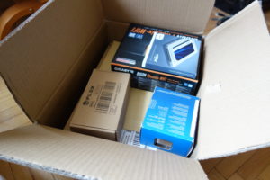 options out there, which utilize new technological developments like silent SSDs, built-in graphics, and CPUs that generate much less heat to enable modest builds to be cooled completely by heatpipes, without the need of fans. After comparing the viable alternatives (Streacom FC8 Evo, Akasa Euler), I felt like the H1.S was the best case for me. So I started ordering all the parts a piece or two at a time while waiting on HDPLEX to release their new and improved nano PSU which plugs directly into the ATX connector.
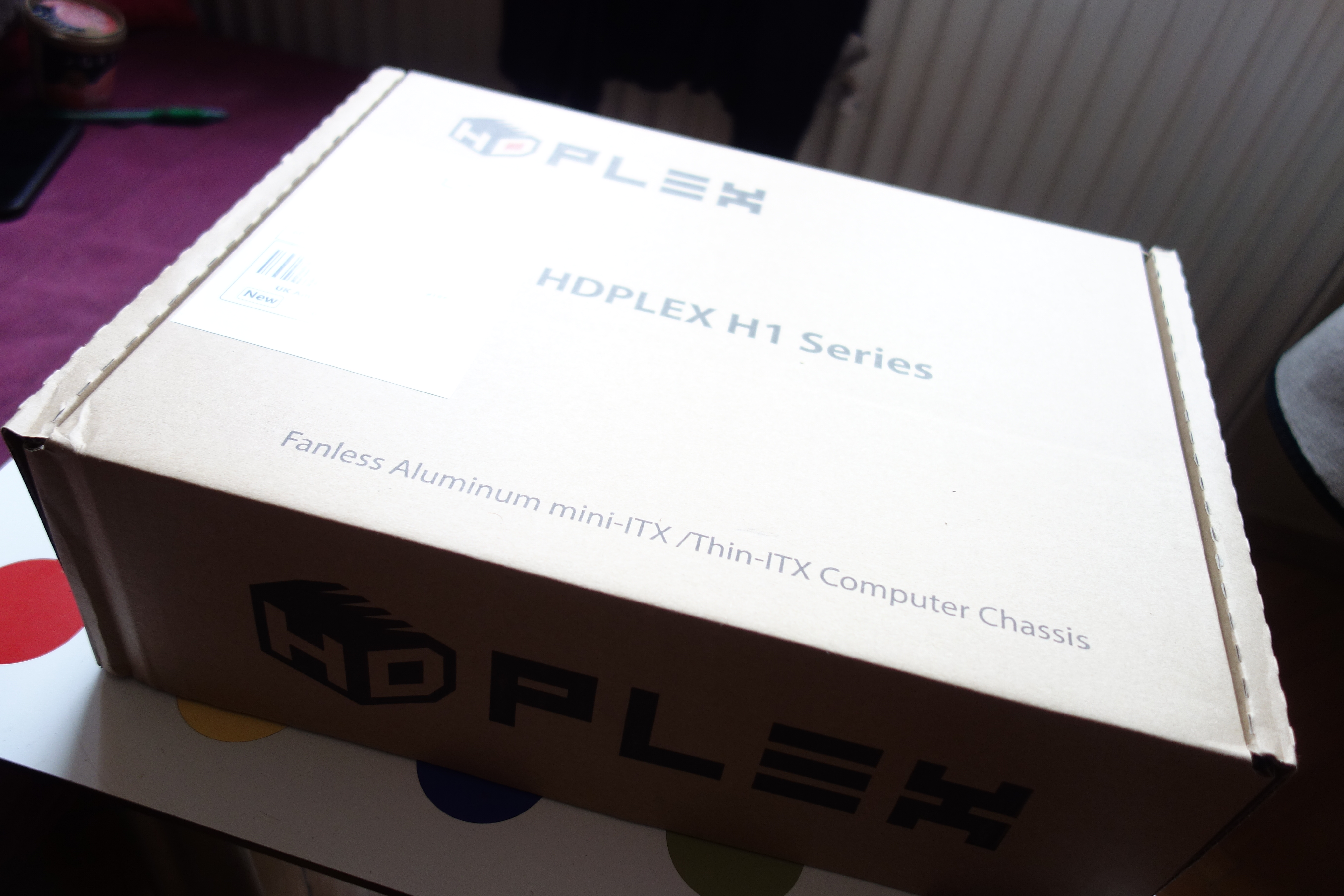
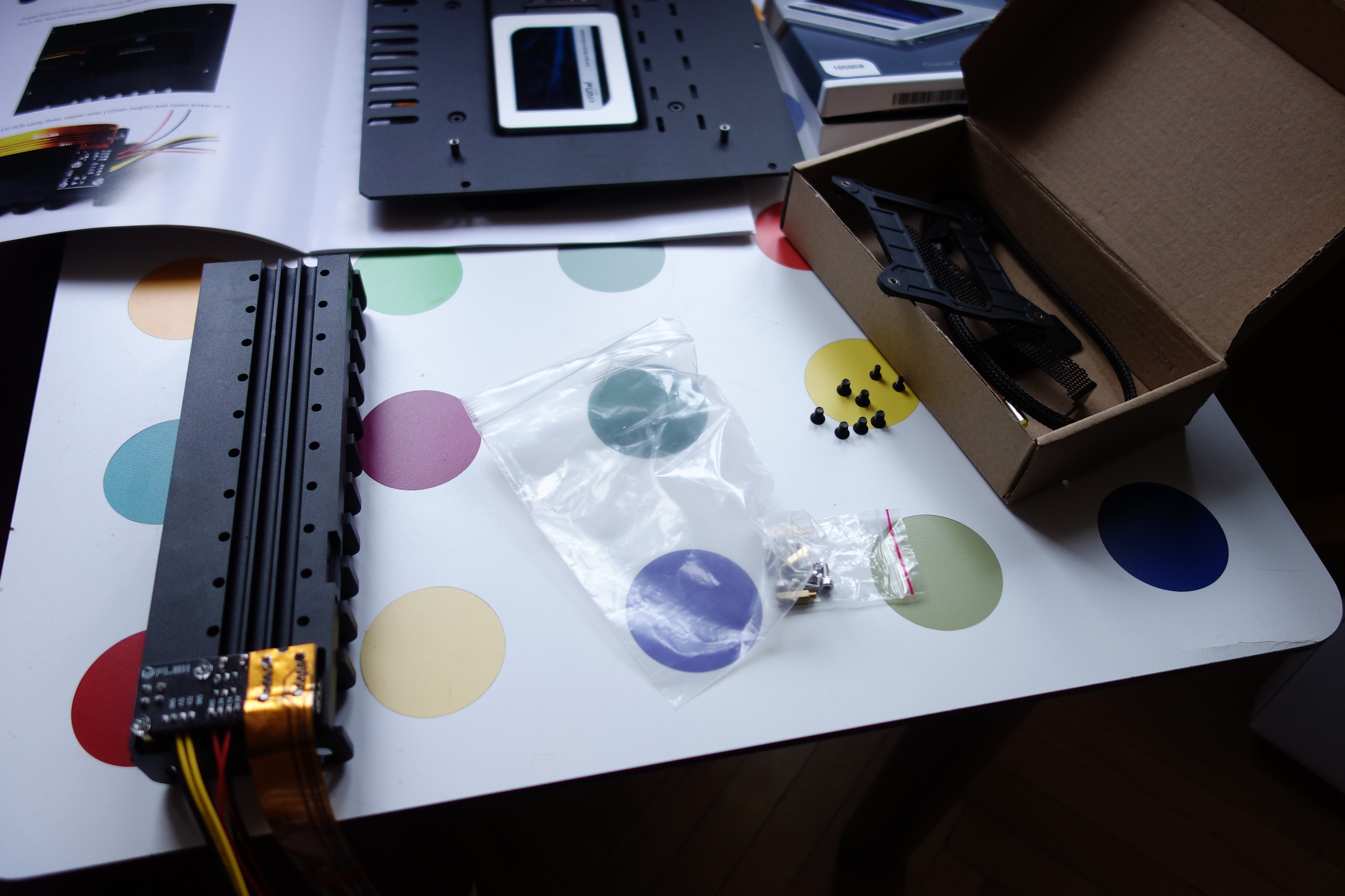
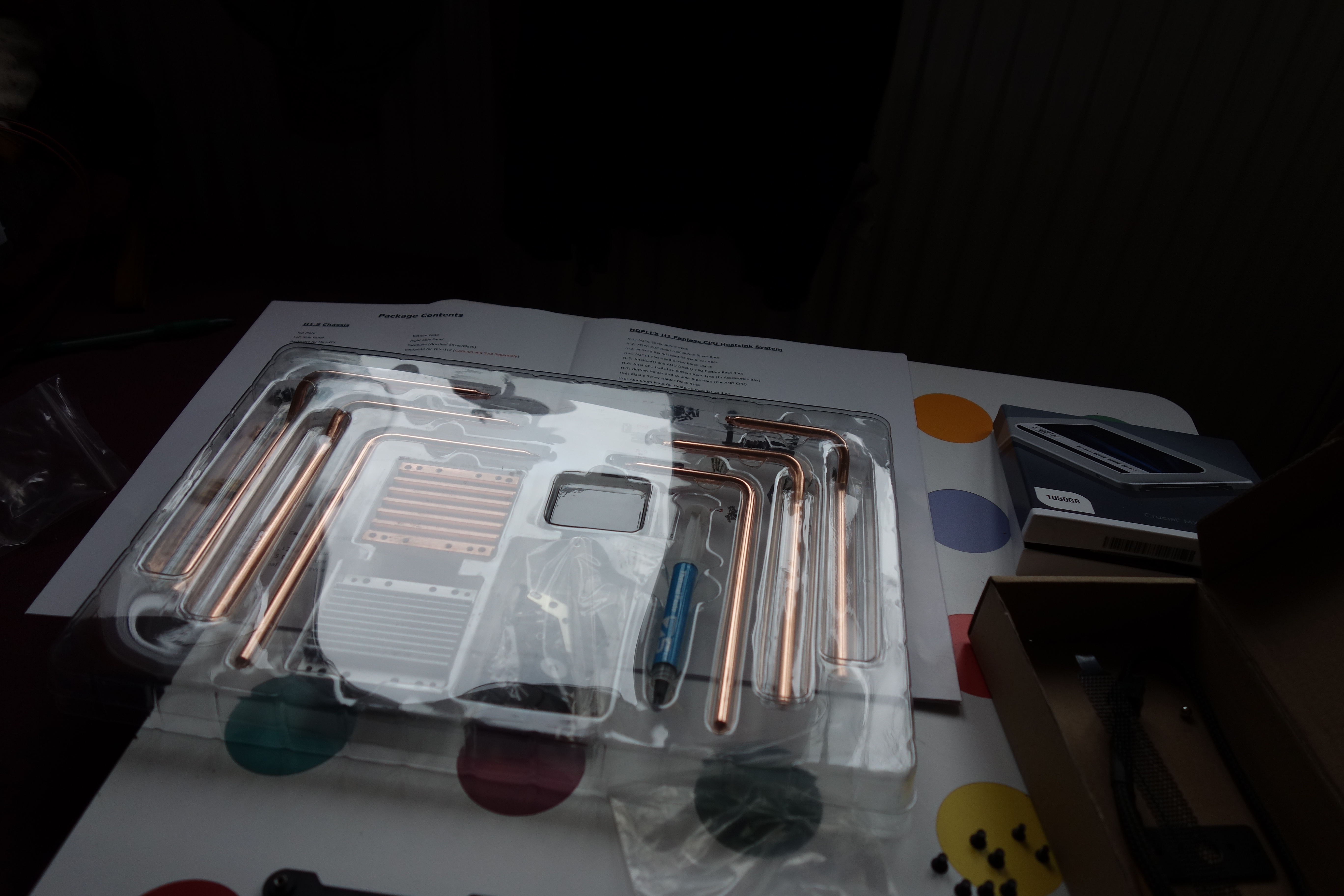
Parts started trickling in, and sometime in January HDPLEX released their new direct-plug 160W PSU, so I 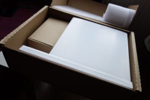 quickly ordered and it arrived from Germany a few days later. Once I’d gotten everything but the RAM, I decided to start building. As others have noted in their reviews, the HDPLEX was well packed and well-provisioned, with nearly everything you need to get up and running immediately (two things seem to be missing, which I’ll talk about later). So now on to the installation.
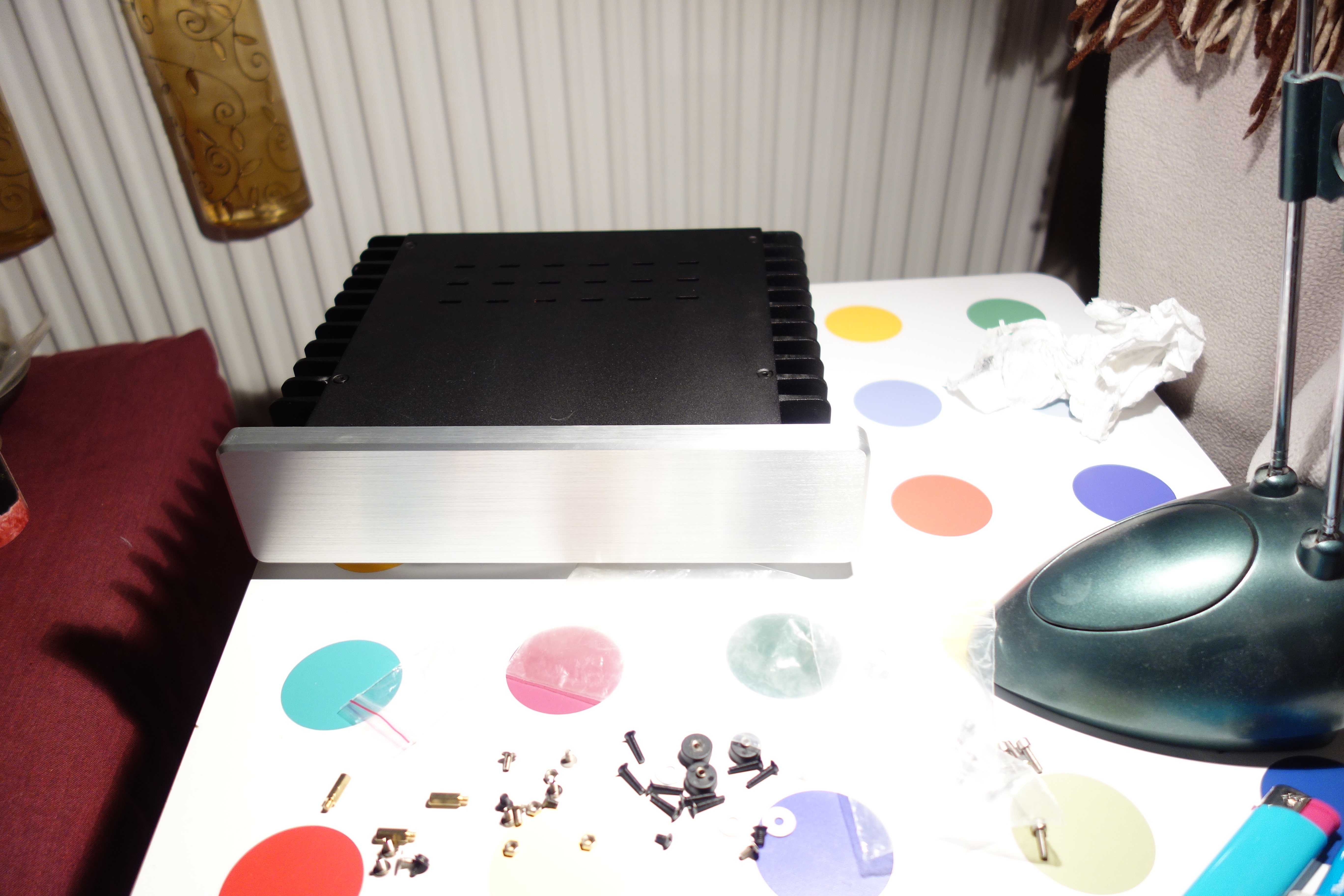
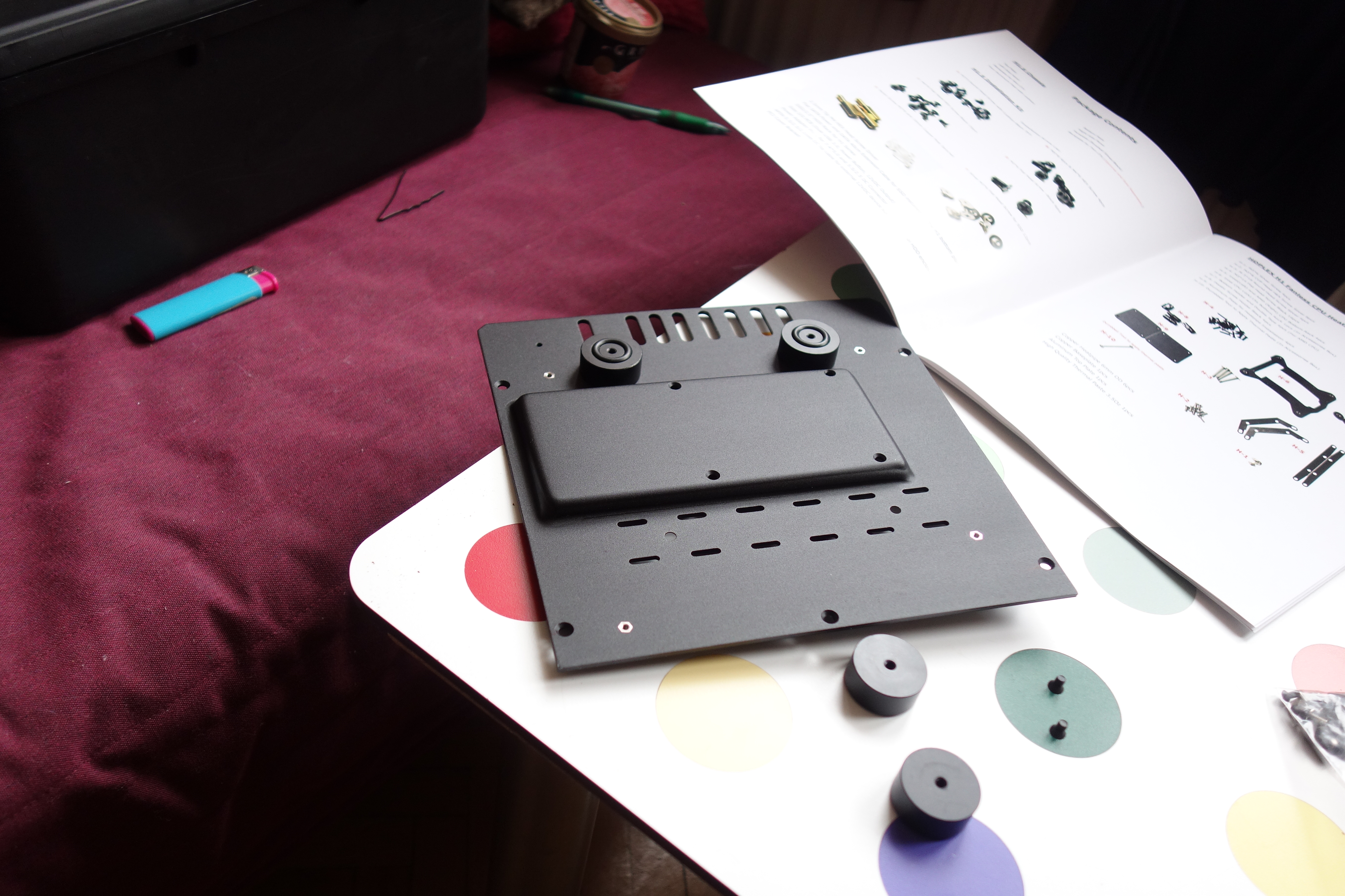
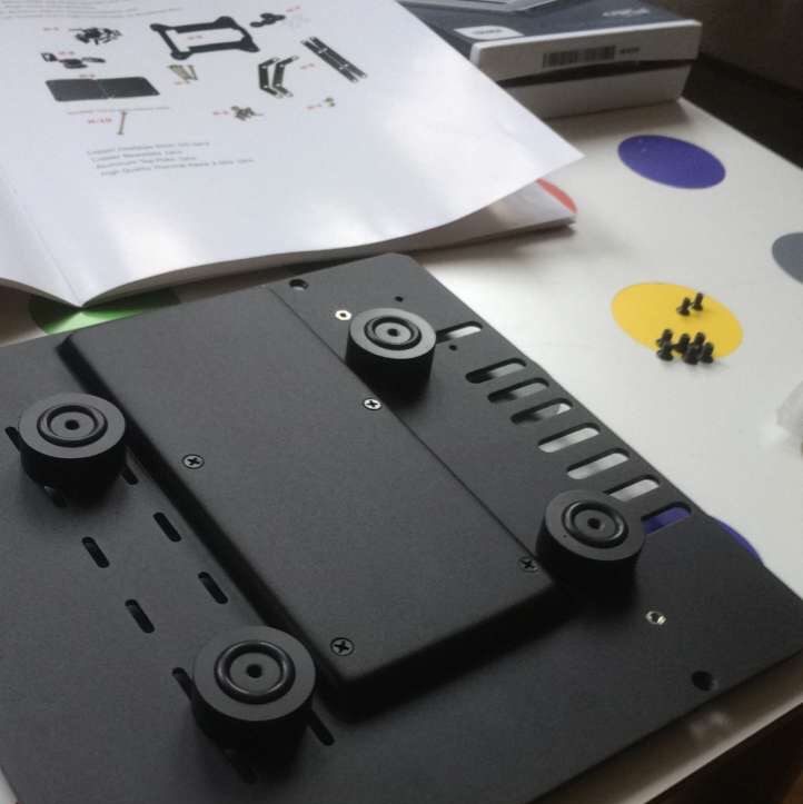
The first step was installing the rubber feet. 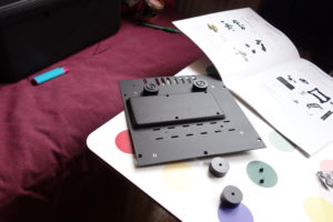 They seem to be very high quality. In previous cases I’ve owned, the rubber feet always take a lot of
  punishment and usually don’t survive that long, after they are slid across the floor, and otherwise put under stress. But these were actually solid aluminum pieces that are screwed in (not glued) and there are rubber grommets in a groove on the feet that can be removed if desired, or kept on to make the feet a little grabbier.
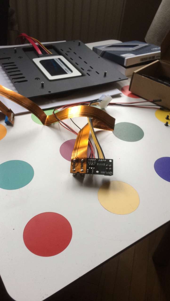
Next it was time to install the hard drive into the “bathtub” underneath where the motherboard will go. HDPLEX 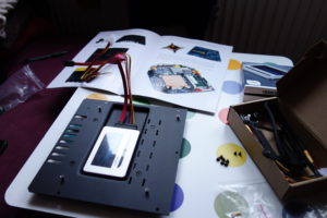 supplies a one-piece SATA/power cable that, at first glance, appears to have part of one of its edges scraped off, which made me think there was an issue, but then I came to realize that part of it was probably shaved off so that it would slide in underneath the SSD more easily, and in fact, it did. The connector is 4-pin molex though, not SATA power, and I only saw one of those connectors on the PSU.
Next, the guide says to install the side I/O PCB using the nylon screws and risers. 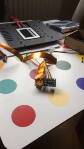 The one screw underneath the data cable is a little difficult to access and screw in without affecting the data
  cable, but after a couple of tries I was able to gently hold the cable out of the way while inserting the screw (so you don’t pinch the data cable). I would later find out I made a mistake here, as the USB ports, power button and 4-pin power seemed to be jutting out more than they should, and I realized that there are two sets of risers in the package, and I’d used the
 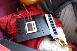 shorter set. Later, I switched out the risers and after that, the ports fit flush against the side panel. But in so doing, one of the nylon screw heads (the one underneath the data cable) twisted off, so now there is a nylon screw holding it on, but it can’t be removed. Hopefully, there will be no need in the future to remove this side PCB again. I suppose in a way it was beneficial, as the data cable won’t get bent laying over a screw.
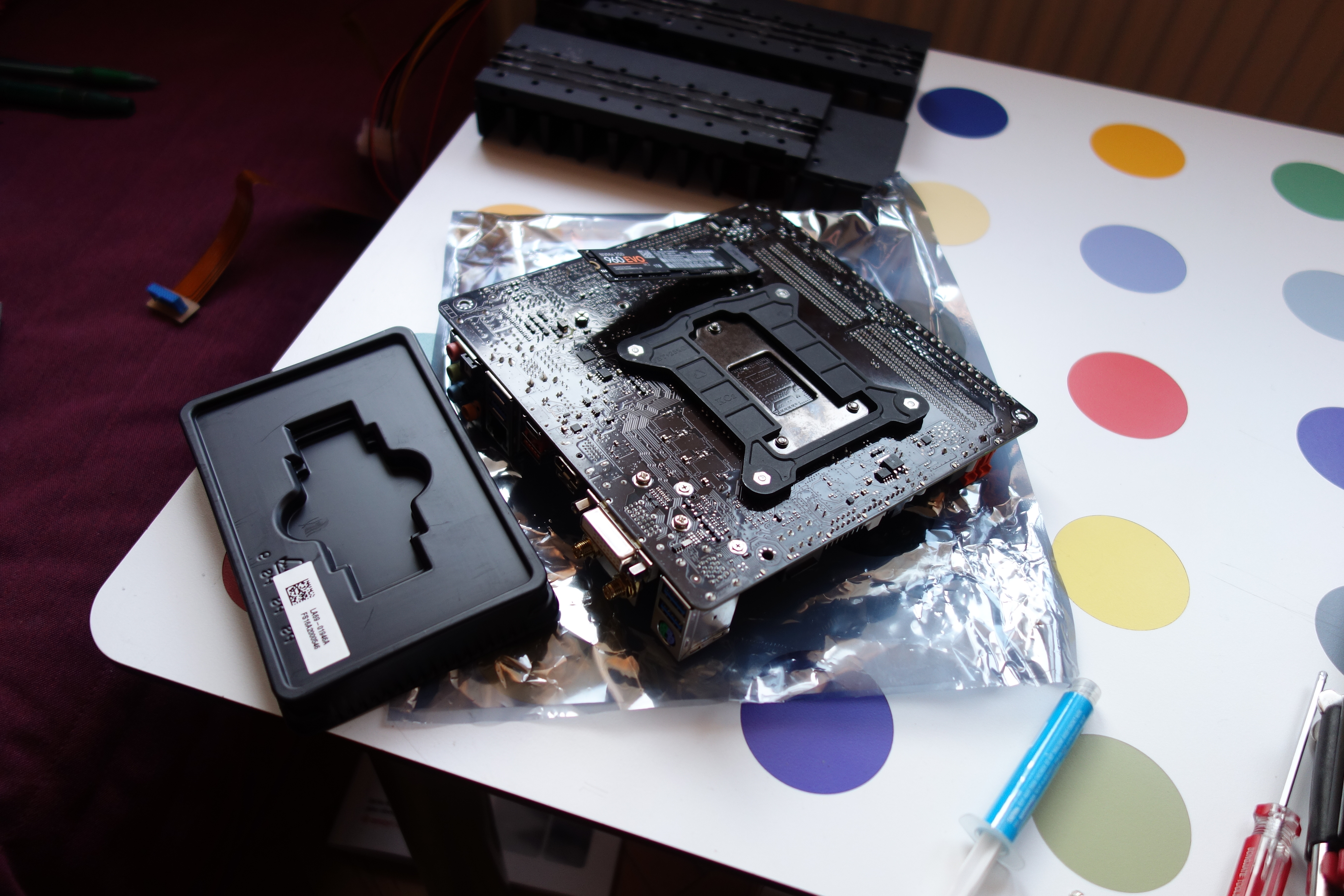
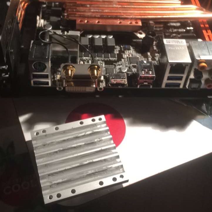
Next, it was  time to prepare the motherboard. First, I installed the M.2 drive and CPU backplate to the rear of the motherboard. No problems.
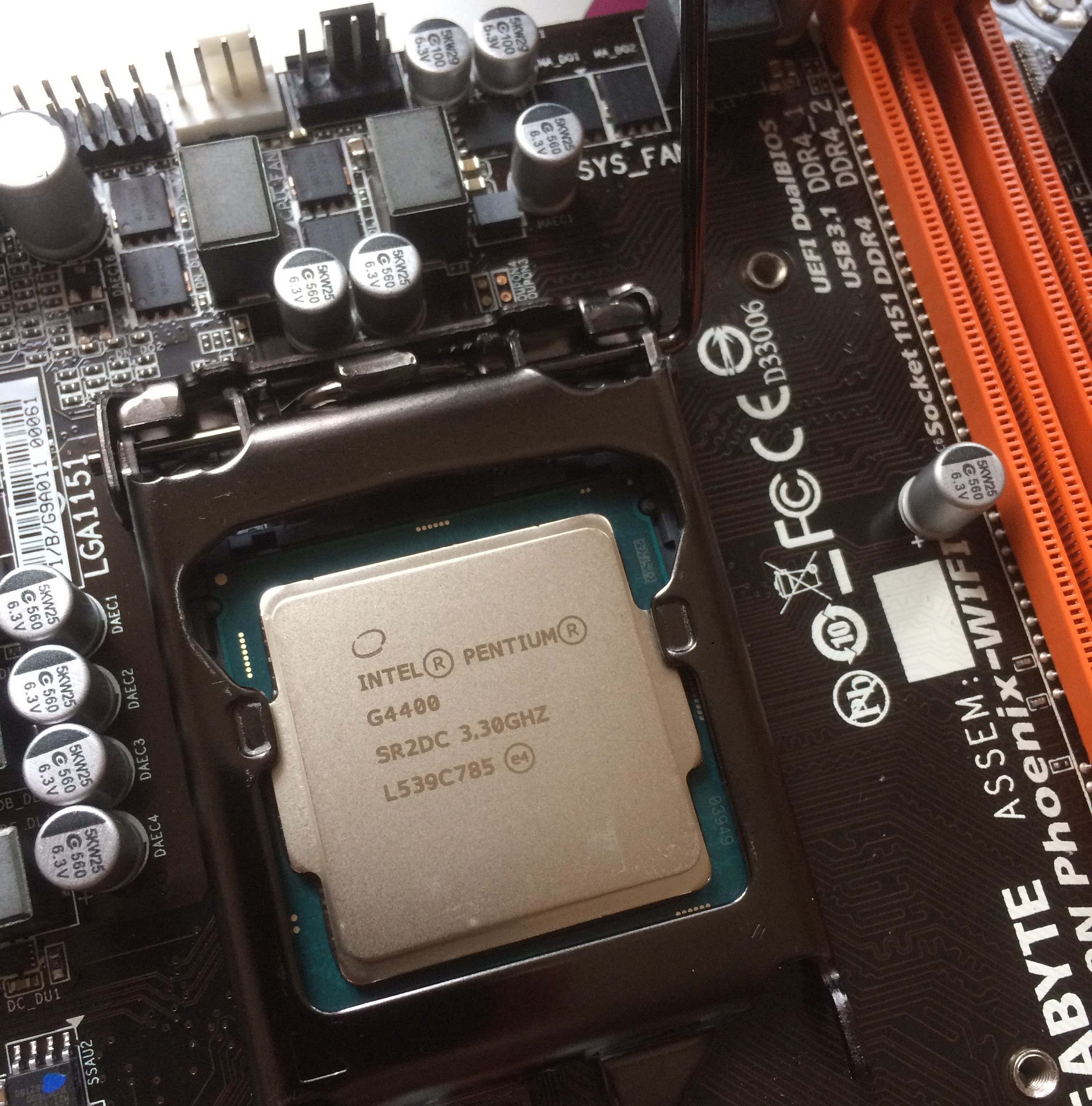
  Then I turned over the board and inserted the CPU into the socket. Again, smooth sailing. After that, I started on the heatsink assembly. It was a bit tricky to figure out the orientation of the four plastic screw holders that connect to the backplate, but eventually I looked at enough pictures and figured it out. Then you screw on the
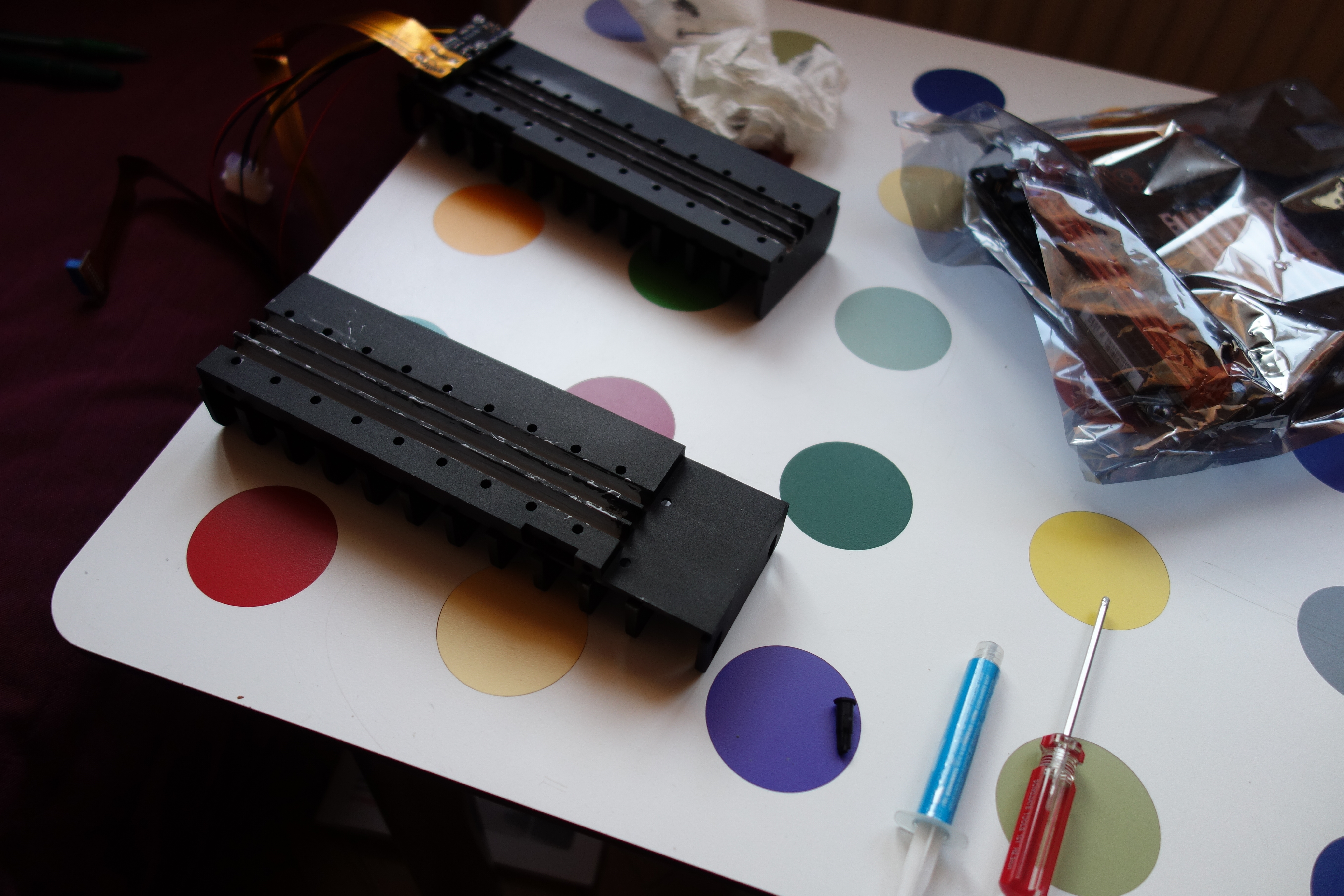
 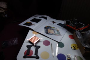 heatsink mounts. As you can see, I first put them on the wrong side, but realized my error and corrected it. You are then instructed to
 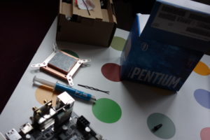 apply a thin layer of thermal paste to the shiny side of the heatsink, and secure it with the backplate and screws, being careful not to tighten too much. The instructions don’t mention that the CPU doesn’t make contact with he entire base so there is no need to apply thermal paste all the way to the edges. A thin square in the middle with some wiggle room should be sufficient.
Next, you affix the side panels. Easy you say? Well I screwed this  up too, mounting them upside down. I didn’t realize this until it was time to add the SSDs above the CPU, and the holder plate didn’t fit right. That’s when I realized that there is a groove into which the SSD plate slides which keeps it from poking out above the side panels. When you add the side panels, if the top of the side panel is flat, you have it upside down. This change also moved the side I/O to the other side of the case.
Before you add the side panels, the instructions say 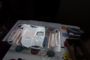 to apply a thin layer of thermal paste to the grooves that run along the side,
 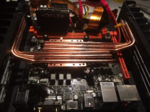 but I think this step should come later. In my opinion, before any thermal paste is applied anywhere except the CPU surface, you should figure out how you are going to orient your heatpipes. There are at least 3-4 heatpipe configurations that work to varying degrees, but most of them had some drawbacks. The
 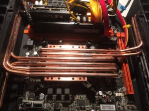 instructions say to orient the heatpipes towards the front, but this left a few centimeters of heatpipe hanging over the end of the groove in the side panel. Then I tried a mixed way, with one heatpipe to the rear which should theoretically increase efficiency, but ended up going with the third option, all heat pipes headed to the rear, towards the I/O.
 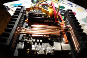 This solution allowed all the heatpipes as much surface contact as possible
  without having any pipes hanging over the edge. The reason I say wait to apply thermal paste is because a) there’s no point in putting thermal paste on grooves where there are no heatpipes and b) you don’t have to clean up a big thermal paste mess where cables have rubbed some off or when you change your heatpipe orientation.
Once you’ve made a final decision on heatpipe orientation, apply t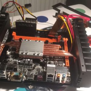 hermal paste only to the side panel grooves where heatpipes will reside and only where they make physical contact. Then loosely install the plates that hold the heat pipes in place, apply a thin layer of thermal paste to the aluminum heatsink top cover, and screw it on to the copper bottom plate. I ran into another issue here: there are two sets of nearly identical aluminum screws, but only one of them works (the smaller ones). I figured this out when some of the screws wouldn’t mount flush. Tighten up both the side plates and the top cover.
And now for the final steps. First, plug the USB3.0 board onto your motherboard. Then plug in the PSU, which is designed to perfectly fit the case. 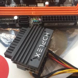 This tiny PSU is amazing to me and along with the M.2 drive shows the progress made in technology since 2008. Next, add your RAM. At this point I added the 7.4/5mm power backplate to the rear panel. There doesn’t seem to be a specific screw for this task.
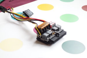 I eventually used a nut and screw to affix the power connector to the back plate, but I’m not sure if it’s correct, as the screws used don’t mount flush like all the other screws. Next, use the provided plate to mount any SSDs you have. The plate, SSDs, RAM, and PSU fit together perfectly. Then connect all the peripheral cables, cross your fingers, and fire it up.
In my case, when I powered up the machine, I had some troubles which I eventually tracked down to one of the memory channels which was not working. To test all the hardware and make sure everything worked, I used the one good RAM channel to install my operating system and check everything out. Everything ran fine and showed CPU temps of 27C at idle, which is fantastic. Since there is no sound on the board, I plugged a fan into one of the fan headers to determine if the board was getting power.
However, there seems to be two issues connected with the side panel. One, external power is also 4-pin molex, and there is only one 4-pin adapter on the power supply, which means you can only plug in either the bathtub SSD or the external power connector, but not both. I’m sure they make 4-pin to SATA power adapters, but none are included in the box. I looked in my cable and connectors odds and ends and didn’t find one. Also, the side I/O 4-pin to 5.5/2.5 actually includes a 5.5/2.1 plug, but all my 12V external enclosures use 5.5/2.5. The site says it’s “dual-purpose” and that it is specified as “5.5/2.5/2.1” but I haven’t yet figured out how to have it work for 5.5/2.5. And the point is moot anyway because I need a SATA to 4-pin molex adapter to power it.
So as of today, I’m still waiting on the RMA of my motherboard to come through. Once that is completed, I should have a PC that I hope will last a long time. The case was the single biggest required expense, but even so, without optional components, this build cost under $500.
Required Components:
HDPLEX H1.S
HDPLEX 160W DC-ATX
Gigabyte B150N Phoenix-WIFI
Intel Pentium G4400 3.3GHz
Kingston HyperX Fury 8GB DDR4 2400
external PSU (laptop-style)
Optional Components:
Samsung 960 EVO NVMe m.2 SSD 1TB
Crucial MX300 1050GB SSD
Startech.com USB3.1 Gen 2 Dual Bay dock
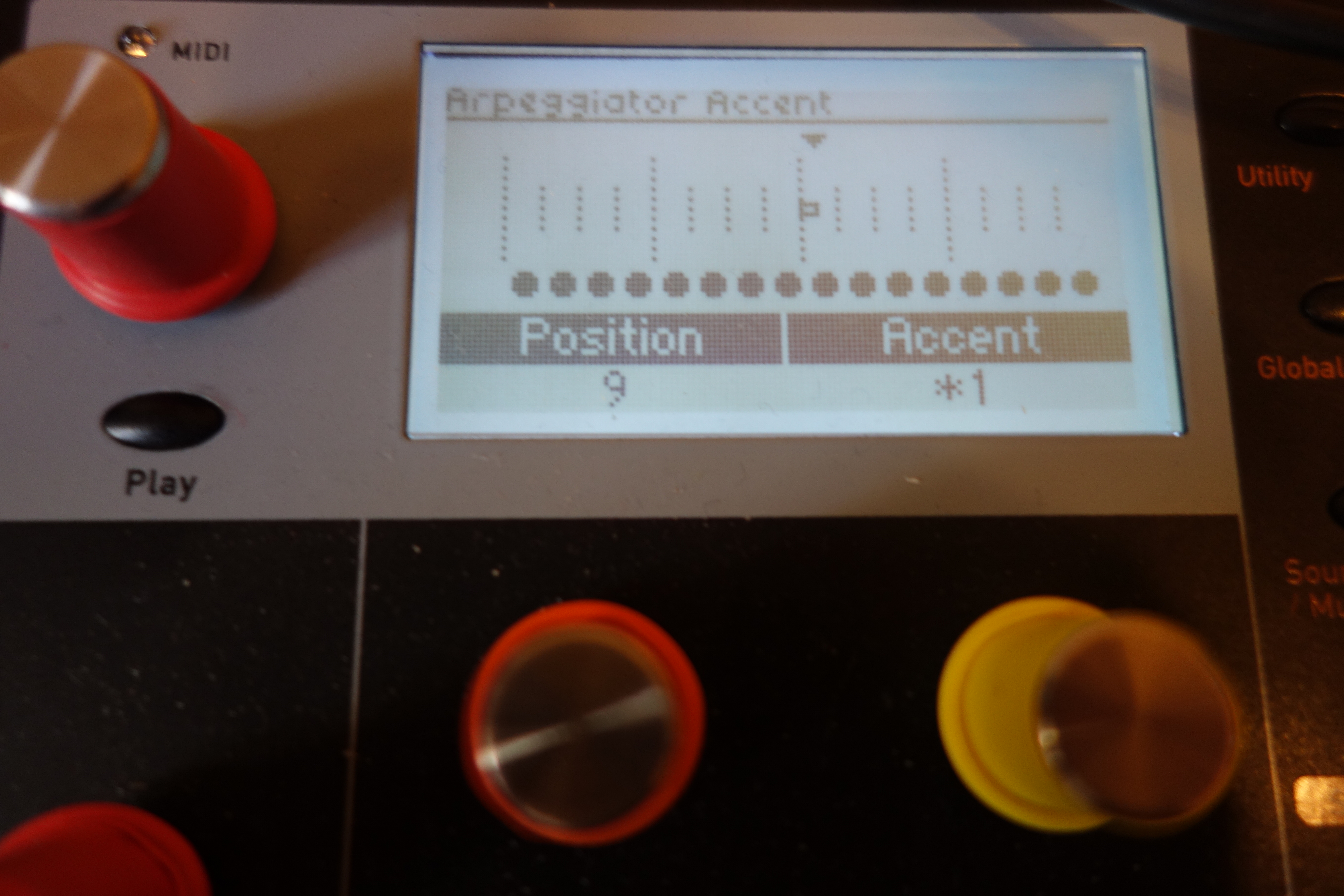
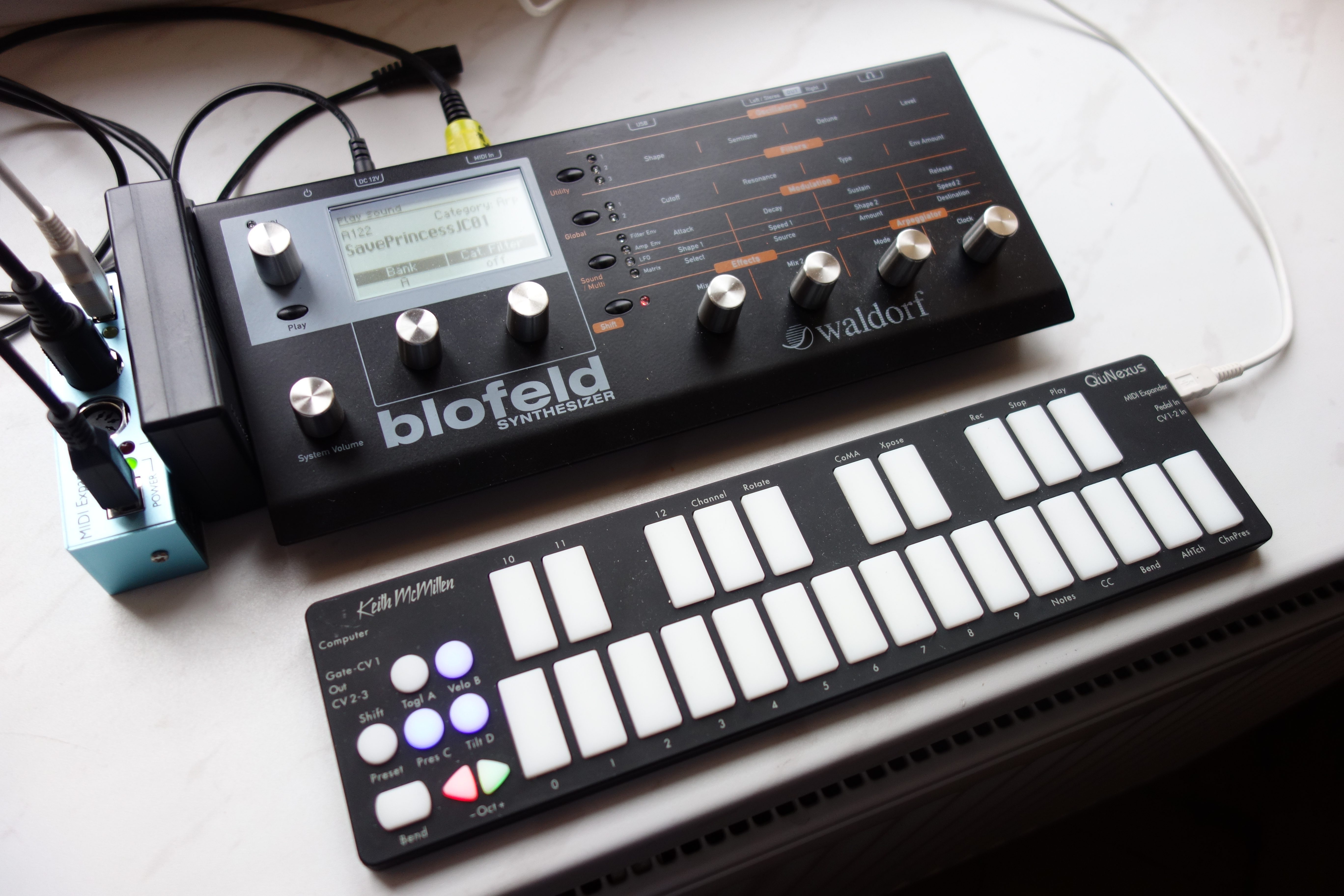
 Let’s see if I can re-create this drum pattern, TNGHT’s “Higher Ground,” using the Blofeld’s onboard arpeggiators. It’s not going to be easy, but I’m sure it’s possible, and probably in more than one way. First thing I did was listen to the original track in super slo-mo and mapped out the basic pattern of kick, snare, & clap and put them into a 16th note grid. There is also a hi-hat, a few different snare patterns and rolls, a vocal sample and a lead that I’ll need to add, but I’ll start with the basic stuff.
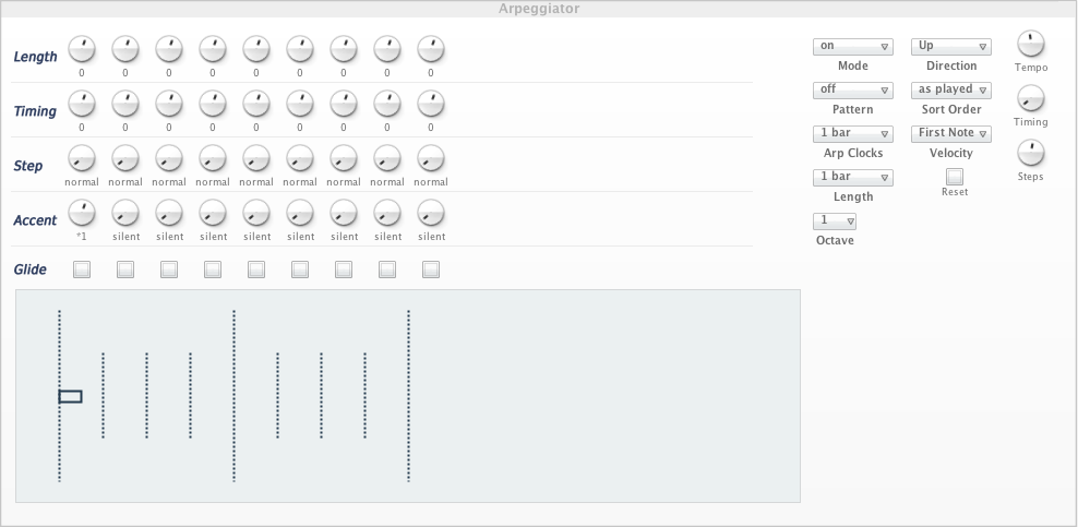
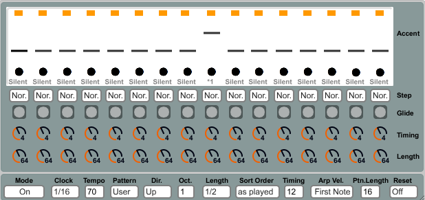
 make sure I set up a 4/4 kick and then laid a 1/8T beat, no user pattern, with a hihat sound over it. Yes, that worked. Then to try and make the beats land properly according to the grid, I made the 1/8T beat a 12 step user pattern like in the photo and it seemed to work well, coming around when it should against the 4/4 beat, so, I thought, just change the sound for this arp pattern to a kick, and try to lay a straight beat over it for the other sounds. Well, that didn’t work because the kick would come around too soon, essentially it’s in 3/4 and everything else is in 4/4 so I couldn’t get everything in the proper time.